
 |
 |
 |
 |
 |
 |
 |
 |
 |
 |
 |
|
|
|
|
|
|
|
|
|
|
|
|
PRODUCT
|
Valve
|


|
Blowdown Valve
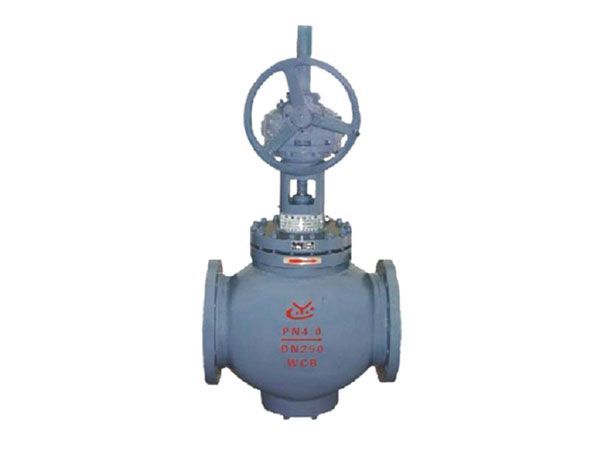
Two National Patents: ZL02222181.6、 ZL97205605.X National Key Product Performance Features 1. Reliable seal: hard -soft dual-material seal ensures zero leakage of gas and liquid media. 2. Throttling function: The multi-stage throttling structural design can not only meet the changes in blowdown flow, but also meet the needs of different operating conditions. Moreover, it effectively mitigates the erosive flow containing heavy moisture and sand particles on the sealing pair of the valve plug. 3. Self-cleaning function: during the valve closure process, the structural design of the valve could achieve blow-off of the valve seat sealing surface and the soft seal pair. This avoids the adhesion of debris on the hard and soft sealing surfaces, ensuring the sealing performance of the valve after blowdown. 4. Automatic debris removal: The debris collection groove between the two O-rings on the valve plug could realize automatic debris removal. This ensures that the outer surface of the valve plug and the inner wall of the valve cage remain clean at all times, preventing the second O-ring from being worn out and ensuring reliable sealing. 5. Slow-pressure idle stroke: Equidistant synchronous slow-pressure idle strokes are set inside the valve. This design ensures that the medium begins to be throttled and discharged only after the valve plug has moved a sufficient distance away from the sealing surface of the valve seat, reducing the erosion force on the sealing surface and effectively protecting it. It ensures reliable sealing, and meets the blowdown requirements under severe operating conditions. 6. The valve plug is fitted with a balancing hole:It requires less torque to operate, making it easy and flexible to open the valve. 7. Each valve is shipped with the packing gland bushing pre-filled with grease: which can meet the valve's lifetime use. There is no need to add grease during any stage from installation, pressure testing to commissioning and operation.
Technical Parameters
Structural Diagrams
Material of Major Parts
Application Performance
Previous:Pilot Safety Valve |
|
|
|